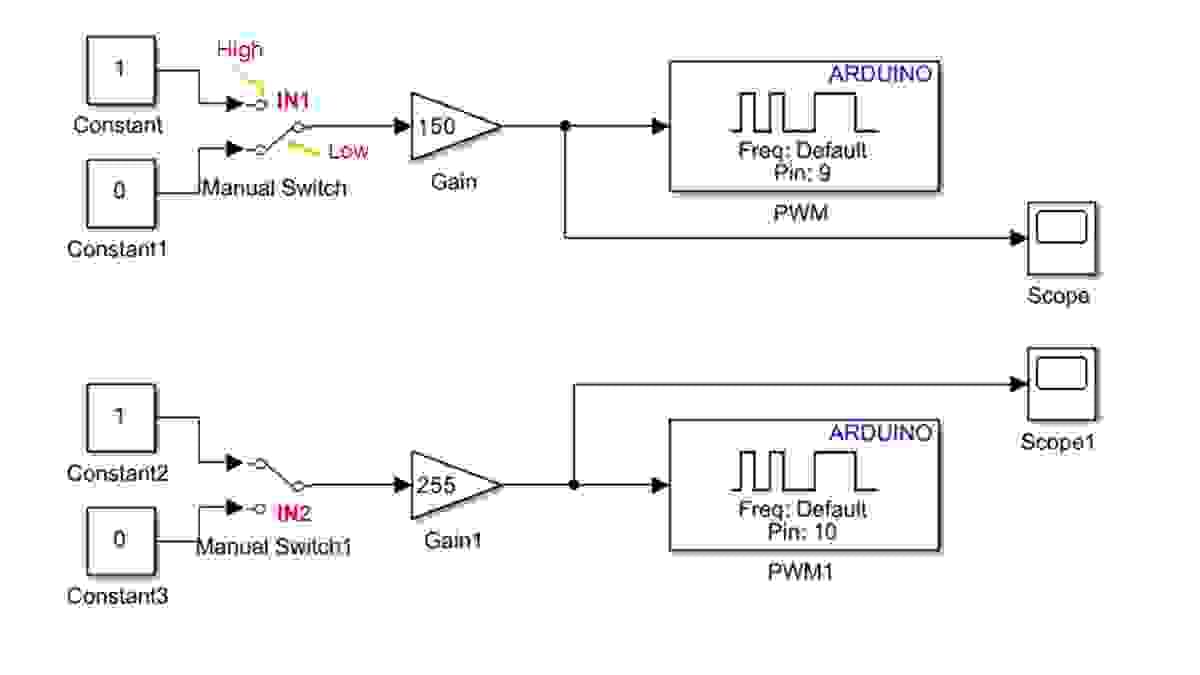
thumbnail image

  • Home
  • Intro
  • News
  • ACE-Box 
    • What is the ACE-Box?
    • Prior Exercises
    • Base + Sense
    • Base + Sense + Actuate
  • Contact
  • …  
    • Home
    • Intro
    • News
    • ACE-Box 
      • What is the ACE-Box?
      • Prior Exercises
      • Base + Sense
      • Base + Sense + Actuate
    • Contact
  • DC Motor

    1. Learning Outcomes

    After completing this Section, you will be able to:

    1. Explain the principles of DC motor polarity control and demonstrate safe and effective operation of a DC motor under bidirectional drive.
    2. Design, implement, and validate an H-bridge circuit to achieve bidirectional (polarity-reversing) control of a DC motor.
  • 2. Hardware Set-Up

    xxxx

    Note that while the ACE-Box can be used for all the exercises, it is not required and only the individual components are needed.

    Required hardware for this exercise:

    • Supported Arduino Uno board
    • H-bridge
    • DC gearbox (50:1) 6V motor
    • USB cable
    • 9V battery
    • 9V power jack
    • 2 x male-male wires
    • 2 x male-female wires
    • 2 x male-copper wires

    Set-up the hardware as shown and following these steps:

    1. xxxx
  • Download Now

    Download the PDF version of the exercise

    DOWNLOAD NOW
  • 3. Simulink Setup

    The Simulink block diagram for the H-bridge algorithm design is given, with the logic used for controlling the 'forward' and 'reverse' motion of the DC motor. Please note
    that to implement this in real-time on a physical system, the switches would
    need to be external, or logic built into Simulink. Based on the electronic circuit set-up
    provided above, the operation of the H-bridge polarity ‘control’ operates as
    follows:


    1. ClockwiseMotion

    • Set IN1 to High
    • Set IN2 to Low

    2. CounterclockwiseMotion

    • Set IN1 to Low
    • Set IN2 to High

    3. Stop Motion

    • Set both IN1 and IN2 to Low
    • Set both IN1 and IN2 to High

    Once, set-up and operating withinSimulink, perform the following:

    1. Changethe switches as detailed above and view the scopes to explore how the signals are changing
    2. Asthe PWM has values between 0 and 255 (150 and 255 are initially given below),
      investigate changing the numbers within the gain blocks to alter the speed of
      the DC motor.
    Section image
  • Download Now

    Download the PDF version of the exercise

    DOWNLOAD NOW

Advancing automatic control engineering (ACE) education through global collaboration

Powered By
Cookie Use
We use cookies to ensure a smooth browsing experience. By continuing we assume you accept the use of cookies.
Learn More