Tactile Button Switch Exercise | ACE-Lab Tactile Button Switch Exercise
Developed by Dr James E. Pickering
The video below shows the tactile button switch exercise in action. Follow the steps on this page to build the hardware, configure the Simulink PWM model, generate the code, and test how pressing the tactile switch completes the LED circuit path.
1. Learning Outcomes
After completing this exercise, learners should be able to apply a Simulink Arduino workflow to an LED circuit controlled through a tactile push-button switch.
Use the Simulink Arduino support packageBuild a simple hardware-linked model for an LED circuit that includes a tactile push-button switch.
Configure Arduino pin 9 for PWM outputUse Arduino Uno pin 9 to drive the LED circuit through the tactile switch, resistor, and LED path.
Apply the PWM model structureConfigure the Sine Wave, Abs, Slider Gain, PWM, and Scope blocks used in the tactile switch exercise.
Deploy and test the tactile switch behaviourGenerate code, run the model on the Arduino Uno, and observe how pressing the switch affects the LED.
2. Hardware Set-Up
The exercise involves connecting an LED to a tactile button switch that controls whether the LED circuit is complete through physical force on the switch. The ACE-Box can be used, but only the individual components listed below are required.
Required hardware:
- Arduino Uno board supported by Simulink
- USB cable Type A to Type B
- Breadboard
- LED
- 220 Ohm resistor
- 2 × male-to-male breadboard wires
- Tactile button switch
Assembly guidance
Place the tactile button switch across the breadboard centre gap so the switch legs sit on separate internally isolated sides. Route Arduino pin 9 through the tactile switch, then through the resistor and LED to ground.
1Insert the tactile button switch so its legs are positioned across the centre gap of the breadboard, with each pair of legs on opposite sides.
2Use a male-to-male jumper wire to connect pin 9 on the Arduino to one leg of the tactile switch.
3Insert a 220 Ohm resistor so that one end is in the same column as the opposite leg of the tactile switch. Place the other end of the resistor in a separate row.
4Connect the long leg of the LED, the anode, to the free end of the resistor. Connect the LED cathode to an Arduino GND pin using a jumper wire.

Circuit diagram for the tactile button switch exercise. 3. Simulink Set-Up
In this part of the exercise, you will develop the PWM-based Simulink model used to drive Arduino pin 9. The tactile switch is added in the hardware path, so no extra Simulink input block is required; the model generates the LED command while the switch controls whether the circuit is complete.
Use a Sine Wave block
Add a Sine Wave block from Sources and connect it to an Abs, absolute value, block from Math Operations.
Add a Slider Gain block
Connect a Slider Gain block from Math Operations. Set the upper limit to 255, which corresponds to 5 V on the Arduino Uno.
Add PWM and Scope blocks
Add a PWM block from Common in the Simulink Support Package for Arduino Hardware and connect three Scope blocks from Sinks.
Deploy the model
Run the code-generation workflow to deploy the PWM model to the Arduino Uno.
Test the tactile switch
With the model running, press and release the tactile button switch and observe how the LED turns on only when the circuit path is complete.
Key properties to modify
- Sine Wave, sine type → Set to sample-based
- Sine Wave, samples per period → Set to 300
- Sine Wave, sample time → Set to 0.01 seconds
- Slider Gain, high limit → Set to 255
- All other properties may remain at their default values
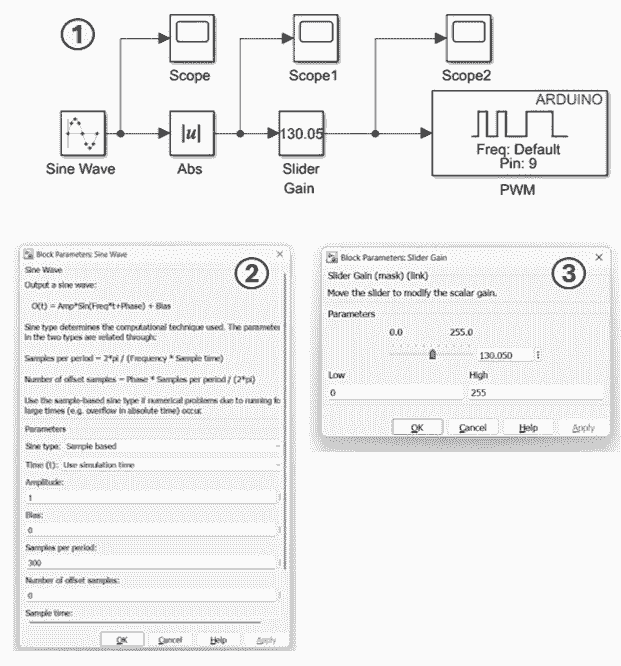
Simulink set-up for the Tactile Button Switch exercise, using the same PWM-based model structure as the LED PWM task. 4. Running Simulink Code Generation
Configure the model for Arduino Uno hardware and deploy it so the PWM signal runs directly on the board. The tactile button switch then controls the physical continuity of the LED circuit.
Connect the Arduino board
Connect the Arduino Uno to your computer using the USB Type A to Type B cable.
Open Model Settings
In Simulink, open Model Settings by selecting Modelling → Model Settings.
Select the hardware board
Under Hardware Implementation, choose Arduino Uno as the hardware board, then click Apply and OK.
Confirm the Hardware tab
Check that the Hardware tab appears in Simulink after the target board is configured.
Deploy the model
Set the simulation stop time to inf, then use Monitor & Tune to compile and deploy the model to the Arduino.
Test the tactile switch
Once the model is running, press and release the tactile button to complete and interrupt the LED circuit path.
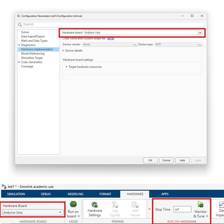
Hardware implementation and Monitor & Tune configuration for Arduino deployment. 5. Additional Exercises
After completing the main task, learners can extend the exercise by changing the PWM behaviour or adding another switched output.
Exercise 1: Change the brightness pattern
Modify the Sine Wave and Slider Gain settings so the LED brightness changes at a different rate. Test how the tactile button affects the revised pattern.
Exercise 2: Add a second LED path
Add a second LED on another Arduino output pin and compare how the tactile switch affects one LED path versus the other.
6. Concluding Remarks
This exercise extends the PWM LED workflow by adding a tactile button switch to the hardware circuit. The result demonstrates how a physical switching element can control whether the LED path is complete, even while the Simulink model continues to generate the PWM command.
By combining model-based PWM output with a tactile switch in the circuit path, learners reinforce their understanding of circuit continuity, Arduino pin use, and the relationship between Simulink deployment and practical embedded hardware behaviour.
Powered By