

2. Hardware Set Up
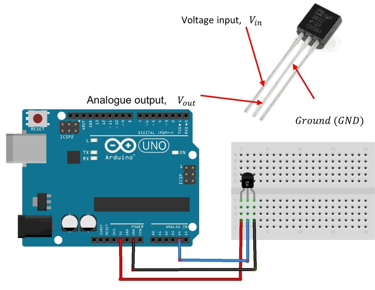
The exercise involves connecting a temperature sensor to an Arduino Uno analogue input and calibrating it using the sensor datasheet to measure temperature accurately.
Note that while the ACE-Box (Base + Sense) can be used for all the exercises, it is not required and only the individual components are needed.
Required hardware for this exercise:
- Arduino Uno board (supported by Simulink)
- USB Cable Type A to B
- Breadboard
- Low voltage temperature sensor (TMP36)
- 3 x male-male wires
TMP36 Temperature Sensor Specifications
- The TMP36 is an analogue temperature sensor designed by Texas Instruments.
- The temperature sensor operates within a voltage input (terminal 1) range of 2.7V to 5V and can function in an operating temperature range of -40 to +125 degrees Celsius
- The analogue output (terminal 2) is connected to an Arduino analogue pin, with terminal 3 being the ground.
Set-up the hardware as shown and following these steps:
- Connect the analogue output of the TMP36 (terminal 2) to an analogue input pin on the Arduino Uno (A4 is used in the example circuit).
- Connect terminal 1 of the TMP36 to the 5V supply pin on the Arduino Uno.
- Connect terminal 3 of the TMP36 (GND) to a GND pin on the Arduino Uno.
3. Simulink Set Up
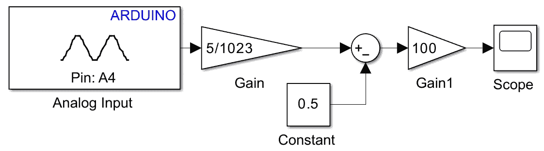
The complete Simulink diagram (i.e., algorithm design) for the hardware described above is provided here. This diagram will be explained step by step in this section. The steps to set up the model are as follows:
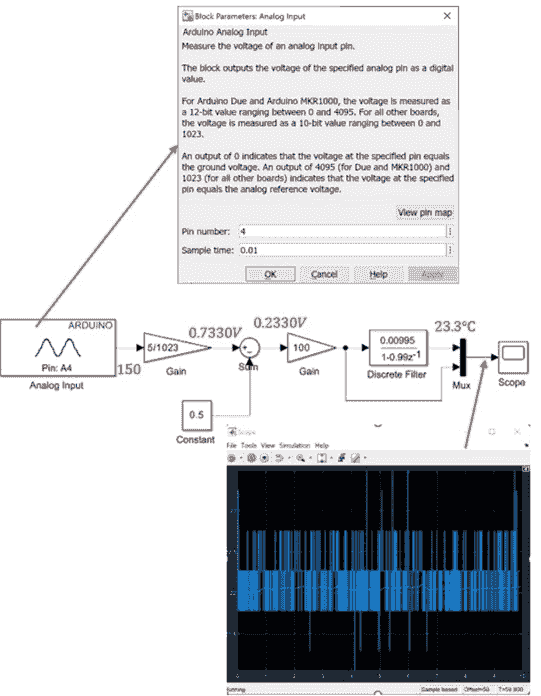
- In the analogue input block, set the sample interval to 0.01 seconds and the Pin number to A4.
- The output from Pin A4 is a 10-bit analogue value that ranges from 0 to 1023. For example, if the output from Pin 4 is 150, the calculation would be (150/1023) = 0.1466. This value represents a ratio between 0 and 1. When multiplied by the 5 (i.e., 5V) supply from the Arduino, the result is 0.7330V.
- As the TMP36 sensor measures temperatures from –40 °C to +125 °C, its output includes a built-in 0.5 V offset (as shown in Table 4 of the Datasheet). To remove this offset in your Simulink model, add a Sum block and a Constant block set to 0.5V, then change the sign configuration in the Sum block to “+–” so that the constant is subtracted from the sensor reading. This adjustment provides the true voltage proportional to temperature; for example, using the value from Step 2, the corrected reading becomes 0.7330 V − 0.5 V = 0.2330 V.
- This adjusted voltage can now be used to calculate the corresponding temperature in Degree Celsius. Referring to the Datasheet (Table 4), TMP36 sensor has a voltage-to-temperature scaling factor of 10 mV per °C. This means that for every 1°C change in temperature, the output voltage changes by 10 mV. To convert the voltage reading into the corresponding temperature, we need to divide by 10 mV (or 0.01V) to determine how many degrees Celsius the voltage represents. This can be done by multiplying the voltage by a factor of 100 via the use of a gain block in the Simulink diagram. Referring to the example, the value obtained above (0.2330V) is then multiplied by 100 to convert the voltage reading into temperature in degrees Celsius, i.e., 23.3°C.
- Deploy the model. Now you should observe the temperature in degrees Celsius of the area the sensor is placed in. You should observe that the temperature measurement signal is noisy and it isn't so easy to read reliable what the value is, e.g., would this signal be useful for reading the temperature of the living room in your house?
4. Low-Pass Filter
A low pass filter is now added to the Simulink diagram. This will basically reject the high frequency signals and allow only the low frequency signals to pass through. The steps to set up the model are as follows:
- Add the Discrete Filter block as shown in the Simulink diagram. Double click and change the coefficients to those given in the Simulink diagram. By default, this will assume you're using a sample time/interval of 0.01 seconds as this is used elsewhere.
- Add a mux so that the filtered and unfiltered signal can be compared.
- Deploy the model. Now you should observe the filtered and unfiltered signals. And importantly, how the low pass filter is eliminating the high-frequency noise and making the signal 'smoother'. This is important as now we have a temperature reading that is useful for when operating control.


Powered By