


LED (Digital) Exercise | ACE-Lab LED (Digital)
Developed by Dr James E. Pickering
The video below shows what your system should do by the end of this exercise. Follow the steps on this page to build the Simulink model, generate the code, and run it on the hardware so that your LED behaves in the same way.
1. Learning Outcomes
After completing this exercise, learners should be able to apply a simple model-based workflow to control a digital output device using Arduino-compatible hardware.
Build a deployable Simulink modelCreate a simple model that connects a Pulse Generator to an Arduino Digital Output block.
Configure Arduino digital output hardwareWire an LED circuit correctly and assign the model output to Arduino digital pin 9.
Apply sample-based timing parametersSet sample time, pulse period, and duty cycle values that produce the required LED behaviour.
Deploy and verify behaviour on hardwareRun code generation, monitor the deployed model, and compare observed LED behaviour with the expected output.
2. Hardware Set-Up
The LED circuit should be assembled so that the Arduino can drive the LED directly from a digital output pin. A resistor must be included to limit current and protect the LED.
Connect Arduino digital pin 9 to the LED circuit through a 220 Ohm resistor. The LED cathode should be connected to GND. This allows the digital output signal to switch the LED between OFF and ON states.
Required hardware:
- Arduino Uno board
- USB cable (Type A to Type B)
- Breadboard
- LED
- 220 Ohm resistor
- 2 × male-to-male breadboard wires
Assembly guidance
Assemble the circuit carefully so that current flows through the resistor before reaching the LED, and ensure that the cathode is connected to ground. A correct wiring sequence makes the later deployment stage straightforward and reliable.
1Connect digital pin 9 on the Arduino to a chosen column on the breadboard using a male-to-male jumper wire.
2Insert a 220 Ohm resistor with one end in the same column as the wire from pin 9 and the other end in a different row.
3Insert the LED such that the long leg (anode) is connected to the free end of the resistor, and the short leg (cathode) is connected to an Arduino GND pin using a jumper wire.
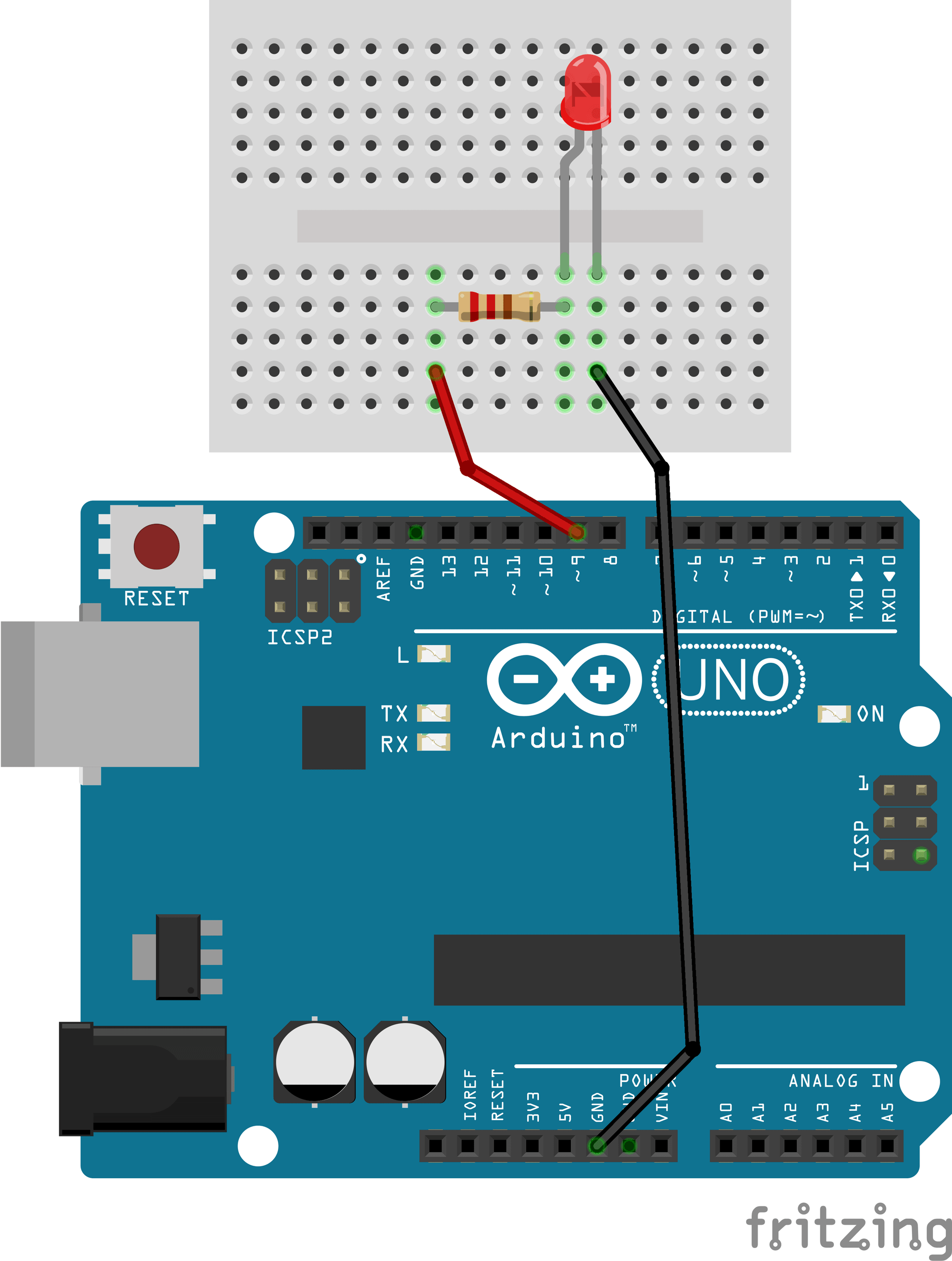
Hardware arrangement for the LED digital output exercise. 3. Simulink Set-Up
In this part of the exercise, you will develop a Simulink model to control the Arduino digital output pin and turn the LED ON and OFF. A Pulse Generator block is used to alternate the output between 0 (OFF) and 255 (ON).
Add a Pulse Generator block
From Simulink → Sources, add a Pulse Generator block to the model.
Add the Digital Output block
From Simulink Support Package for Arduino Hardware → Common, add a Digital Output block.
Connect the model
Connect the output of the Pulse Generator block to the input of the Digital Output block.
Configure the pulse settings
Open the Pulse Generator block parameters and configure Pulse Type as sample based and Sample time as 0.1 seconds.
Assign the output pin
Open the Digital Output block parameters and set the pin number to 9.
Add a Scope block
From Simulink → Sinks, add a Scope block and branch the pulse signal to monitor the generated waveform.
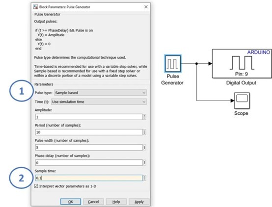
Simulink model showing pulse generation, digital output configuration, and waveform monitoring. 4. Running Simulink Code Generation
In this part of the exercise, you will configure and run a Simulink model to perform code generation on a supported Arduino Uno board.
Connect the Arduino board
Connect the Arduino Uno to your computer using a USB cable.
Open Model Settings
In your Simulink window, open Model Settings by selecting Modelling → Model Settings.
Select the hardware board
From Hardware Implementation, choose Arduino Uno under Hardware board, then click Apply and OK.
Confirm the Hardware tab
A new Hardware tab should now appear in Simulink after the target board is configured.
Check the working directory
Make sure MATLAB is operating and saving in a suitable working directory before clicking Run.
Deploy the model
Confirm that Arduino Uno is displayed, change the simulation stop time to inf, and click Monitor & Tune to compile and deploy the model to hardware.
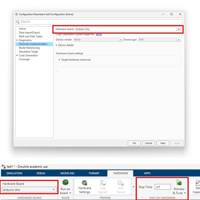
Hardware implementation and Monitor & Tune configuration for Arduino deployment. 5. Troubleshooting Checks
Use these checks if the model deploys but the LED does not behave as expected. They are deliberately practical and focused on the most common lab faults.
The LED does not turn on
Check the LED orientation first: the long leg should connect towards the resistor and pin 9, while the short leg should connect to GND. Also confirm the resistor is in series, not in a disconnected breadboard row.
The LED stays permanently on or off
Re-check the Pulse Generator settings, especially sample-based mode, sample time, period, pulse width, and amplitude. Then confirm the Digital Output block is set to pin 9.
Simulink cannot deploy to the board
Confirm that the hardware board is set to Arduino Uno, the USB cable is connected, the correct support package is installed, and the simulation stop time is set to inf before using Monitor & Tune.
6. Additional Exercises
After completing the main task, learners can extend the exercise by changing timing requirements, adding additional digital outputs, and documenting how their revised behaviour was verified.
Exercise 1: Modify the Timing Requirements
Choose new user-defined values for the LED ON/OFF period and the sample time. Update the Simulink model accordingly and verify that the deployed system operates with the revised timing parameters.
Exercise 2: Out-of-Sequence LED Control
Extend the system by adding a second LED connected to a different Arduino digital output pin.
- First, write a new set of requirements specifying out-of-sequence, phase-shifted LED behaviour.
- Then, implement and deploy the Simulink model to demonstrate asynchronous operation of the two LEDs.
7. Concluding Remarks
This exercise has demonstrated the complete workflow for implementing a simple digital control task using Simulink and an Arduino Uno, from defining requirements through to real-time execution on hardware. By developing, configuring, and deploying a Simulink model to control an LED, learners gain practical experience in linking model-based design with embedded hardware implementation.
The exercise reinforces key concepts including digital input/output operation, timing through sample-based signals, and automatic C-code generation using the Simulink Arduino support package. It also provides a foundation for more advanced tasks involving sensors, actuators, and closed-loop control.
Powered By