


Temperature Measurement Exercise | ACE-Lab Temperature Measurement
This exercise shows how to acquire temperature measurements using a TMP36 analogue temperature sensor, convert the Arduino ADC reading into a voltage, remove the built-in offset, calculate temperature in degrees Celsius, and then improve signal quality with a discrete low-pass filter.
1. Learning Outcomes
After completing this exercise, learners should be able to acquire temperature measurements using an analogue temperature sensor, use a component datasheet to configure the measurement conversion correctly, and implement a low-pass filter to reduce measurement noise and improve signal quality.
Acquire temperature from an analogue sensorUse the TMP36 and Arduino analogue input A4 to obtain a 10-bit ADC reading for temperature measurement.
Implement calibration and filteringConvert ADC readings into degrees Celsius using the datasheet and improve signal quality with a discrete low-pass filter.
2. Requirements
The exercise has the following primary requirements:
1Connect the TMP36 sensor correctly: terminal 1 to 5 V, terminal 2 to analogue input A4, and terminal 3 to GND.
2Acquire the sensor output using the Arduino 10-bit ADC, 0 to 1023 range, with a defined sampling interval such as 0.01 seconds.
3Convert the ADC reading into a temperature reading in degrees Celsius using the sensor datasheet and display the result using a Scope or Display block.
4Implement a discrete low-pass filter to reduce measurement noise.
3. Hardware Set-Up
This exercise involves connecting a TMP36 temperature sensor to an Arduino Uno analogue input and calibrating the reading using the sensor datasheet so that temperature can be measured accurately.
Required hardware:
- Arduino Uno board (supported by Simulink)
- USB cable Type A to B
- Breadboard
- Low voltage temperature sensor (TMP36)
- 3 × male-to-male wires
TMP36 specifications
- Analogue temperature sensor
- Input voltage range: 2.7 V to 5 V
- Operating temperature range: −40 °C to +125 °C
- Analogue output on terminal 2
1Connect the analogue output of the TMP36, terminal 2, to analogue input A4 on the Arduino Uno.
2Connect terminal 1 of the TMP36 to the 5 V supply pin on the Arduino Uno.
3Connect terminal 3 of the TMP36, GND, to a GND pin on the Arduino Uno.
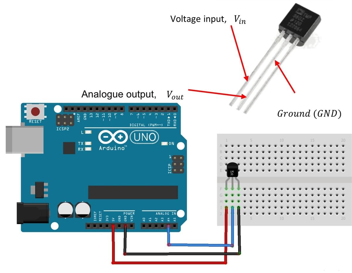
Hardware set-up for temperature measurement using the TMP36 sensor and Arduino Uno. 4. Simulink Set-Up and Temperature Sensor Testing
In this first part of the exercise, the sensor voltage is acquired from A4, converted from ADC units to voltage, corrected for the TMP36 offset, and then scaled into temperature in degrees Celsius.
Configure the Analog Input block
Set the sample interval to 0.01 seconds and the pin number to A4.
Convert ADC output to voltage
The output from A4 ranges from 0 to 1023. Multiply this ratio by 5/1023 to convert the ADC value into volts.
Remove the 0.5 V offset
Add a Sum block and a Constant block set to 0.5 V, then configure the Sum block as +− so that the offset is subtracted from the measured voltage.
Convert voltage to temperature
The TMP36 has a scaling of 10 mV per degree Celsius. Multiply the corrected voltage by 100 to obtain temperature in degrees Celsius.
Display the temperature signal
Use a Scope or Display block so that the measured temperature can be observed in real time.
Deploy and assess the raw signal
Deploy the model and observe the room temperature measurement. You should notice that the raw signal contains visible noise.
ADC to volts: (ADC / 1023) × 5
Corrected voltage: Vin − 0.5
Temperature in °C: (Vin − 0.5) × 100Reference datasheet
Use the TMP36 datasheet to confirm the 0.5 V offset and the 10 mV/°C scaling used in the conversion model.
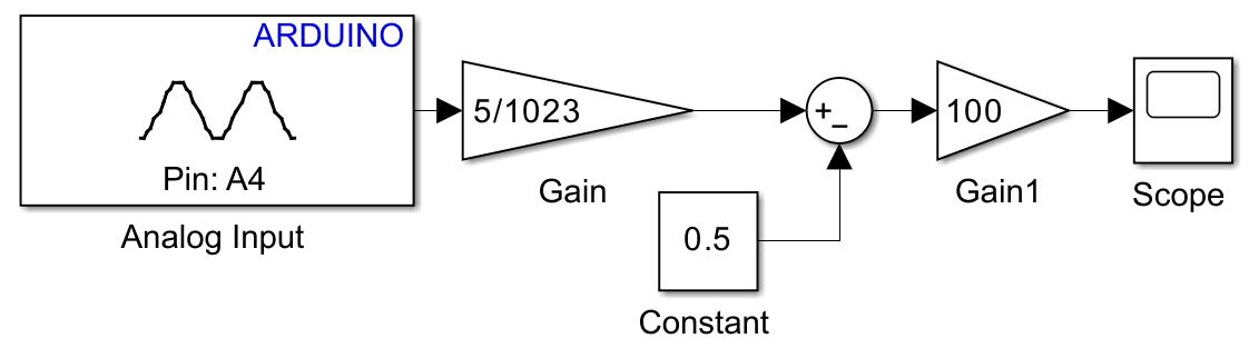
Simulink set-up for temperature acquisition, offset correction, and conversion to degrees Celsius. 5. Low-Pass Filter and Testing
A discrete low-pass filter is now added so that high-frequency noise is reduced while the lower-frequency temperature variation is retained. This produces a smoother and more useful signal for control applications.
Add the Discrete Filter block
Insert the Discrete Filter block into the signal path after the temperature conversion block.
Set the filter coefficients
Configure the filter coefficients as shown in the Simulink diagram. This assumes a sampling interval of 0.01 seconds.
Add a Mux for comparison
Use a Mux block so that the filtered and unfiltered signals can be compared on the same Scope.
Deploy and compare both signals
Deploy the model and observe how the filtered signal becomes smoother than the raw signal while still tracking the overall temperature trend.
Why the filter matters
Raw sensor signals often contain noise. Filtering improves measurement stability and makes the signal more useful for display, decision-making, and closed-loop control applications.
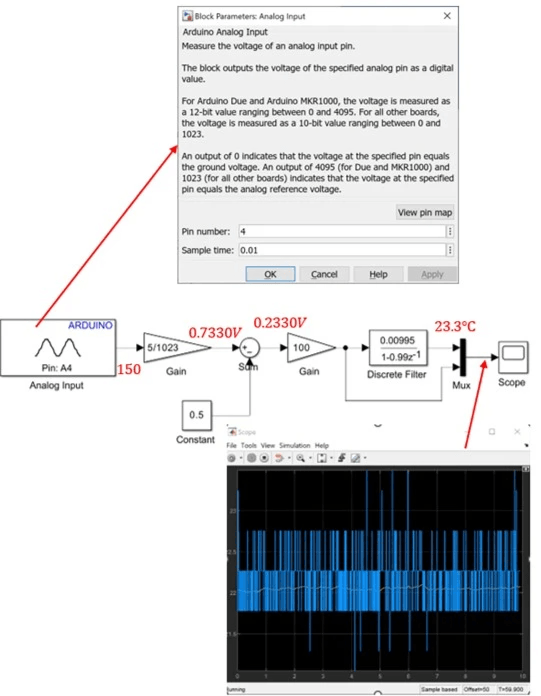
Temperature measurement model updated with a discrete low-pass filter and signal comparison path. 6. Additional Exercises
After completing the main workflow, extend the exercise by changing the conditions and the output interpretation.
Exercise 1: Warm the sensor slightly
Use hand contact or a nearby warm object to observe the dynamic response of both the filtered and unfiltered temperature signals.
Exercise 2: Add a temperature threshold
Add simple logic so that an LED turns on if the measured temperature exceeds a chosen value such as 30 °C.
Exercise 3: Convert to degrees Fahrenheit
Modify the Simulink diagram so that the output is expressed in degrees Fahrenheit rather than degrees Celsius.
7. Concluding Remarks
This exercise demonstrates a complete measurement workflow: analogue sensing, ADC acquisition, voltage conversion, offset calibration, physical-unit conversion, filtering, and display.
The introduction of a discrete low-pass filter highlights the importance of signal conditioning in practical embedded systems. Raw sensor signals often contain noise, and filtering improves measurement stability and usability for monitoring and control applications.