


Hardware Set-Up
The exercise involves connecting an LED to a digital Arduino output pin and controlling its state by switching it on and off.
Note that while the ACE-Box can be used for all the exercises, it is not required and only the individual components are needed.
Required hardware for this exercise:- Arduino Uno board (supported by Simulink)
- USB Cable Type A to B
- Breadboard
- LED
- 220Ohm resistor
- 2 x male-male breadboard wires
Set-up the hardware as shown and following these steps:
- Attach one end of the 220Ohm resistor to output pin 9 on the Arduino board, using the small breadboard and male-male breadboard wires
- Attach the long leg (positive) of the LED to the resistor
Exercise: Algorithm Design – LED Blinking On/Off
In this part of the exercise, a Simulink model will be developed to change the state of the Arduino digital output to being either on or off.
The steps for this part of the exercise are as follows:- Set up the Pulse Generator block (found under Sources) as shown, and connect it to a Digital Output block (found under Common in the Simulink Support Package for Arduino Hardware).
- Connect a Scope block (found under Sinks) to monitor the signal.
- An amplitude of 1 in the pulse generator corresponds to a voltage of 5 V being supplied to Pin 9. (By default, the Digital Output block is assigned to Pin 9).
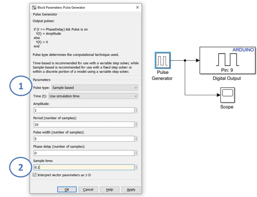
Key Properties to Modify
- Pulse type → Set to Sample-based
- Sample time → Set to 0.1 seconds
All other properties may remain as their default values.
Running Exercise 1 (Code Generation)
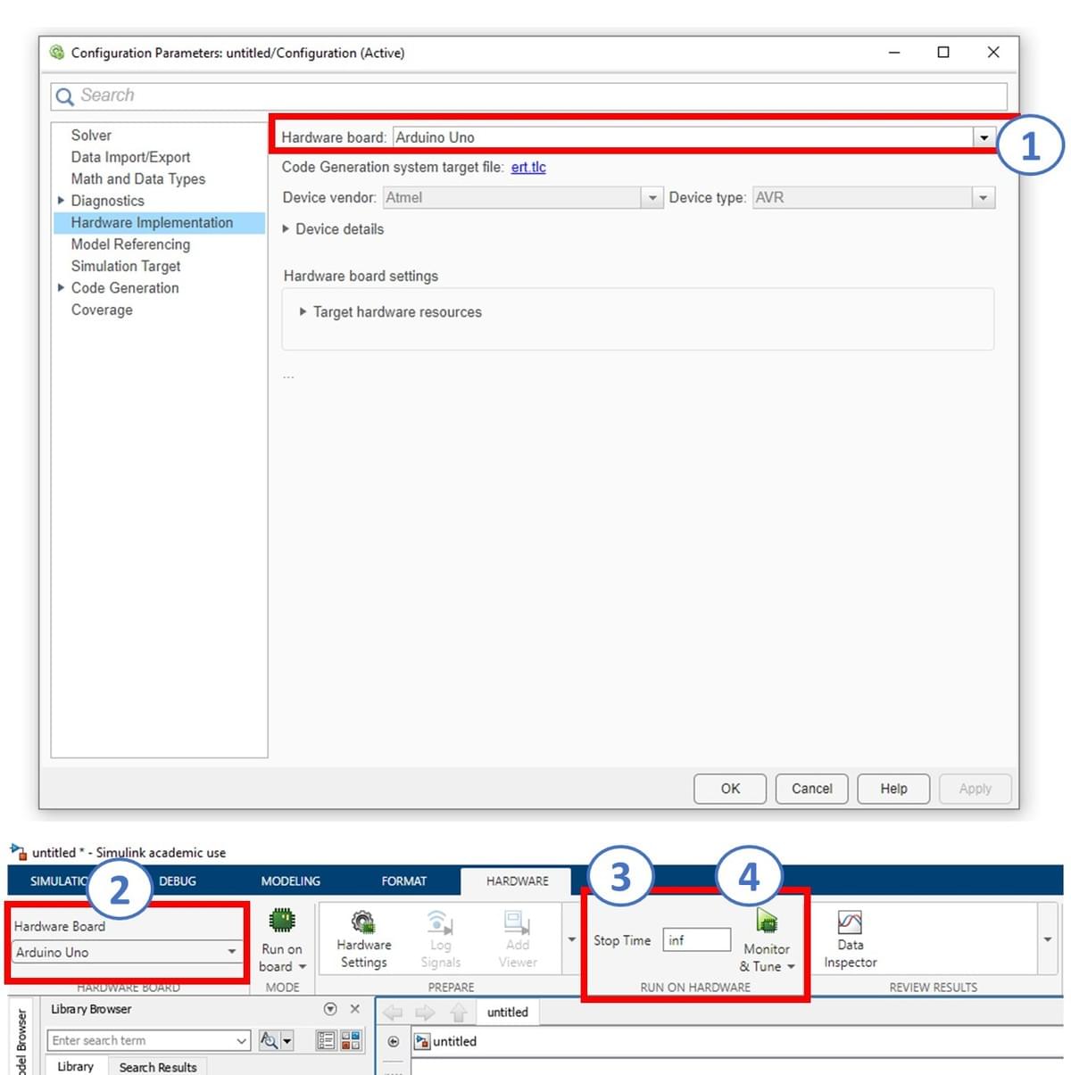
In this part of the exercise, you will configure and run a Simulink model on the supported Arduino Uno board. Using the following steps and as stown in the illustration, undertake the following:
- Connect the Arduino Uno to your computer using a USB cable.
- In your Simulink window, open Model Settings by selecting Modeling → Model Settings. This will bring up the Configuration Parameters dialog (1).
- From the left-hand menu, select Hardware Implementation. Under Hardware board, choose Arduino Uno from the list, then click Apply and OK (1). Note that other boards can be used beyond that of the Ardruino Uno.
- A new Hardware tab will now appear in Simulink. (Ensure your Simulink model is already developed before reaching this step.)
- Important: make sure MATLAB is operating/saving in a suitable working directory before clicking ‘Run’
- Confirm that the Arduino Uno is displayed (2), change the simulation stop time to inf (infinity) (3), and then click Monitor & Tune (4). The Simulink model will now be deployed to the Arduino, compiled into C code, and executed on the hardware.
⚠️If you encounter any errors, click the link below for troubleshooting
Key Properties to Review/Adjust
- Modeling settings
- Selected hardware board → Arduino Uno
- Simulation stop time → inf
- Monitor & Tune configuration
Operation of LED (Digital Pin) Exercise
Observe the LED connected to pin 9 of the Arduino board. It should blink once every second.

Blinking LED!
Click on the Scope block to observe the step input being applied and removed, as defined by the Pulse Generator block.
As you can see, the LED is blinking on and off as expected, in sync with the Pulse Generator.