


Hardware Set-Up
This is the same hardware set-up as used in the previous exercise.
The exercise involves connecting an LED to a digital Arduino output pin and controlling its state by switching it on and off.
Note that while the ACE-Box can be used for all the exercises, it is not required and only the individual components are needed.
Required hardware for this exercise:- Arduino Uno board (supported by Simulink)
- USB Cable Type A to B
- Breadboard
- LED
- 220Ohm resistor
- 2 x male-male breadboard wires
Set-up the hardware as shown and following these steps:
- Attach one end of the 220Ohm resistor to output pin 9 on the Arduino board, using the small breadboard and male-male breadboard wires
- Attach the long leg (positive) of the LED to the resistor
Exercise Algorithm Design – LED Varying Brightness
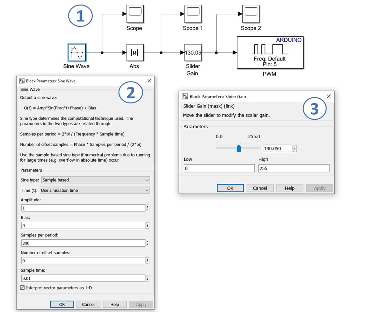
In this part of the exercise, you will develop a Simulink model to control the Arduino PWM output (1). A sine wave signal will be used to vary the PWM values between 0 (off) and 255 (fully on), smoothly adjusting the LED brightness across its full range.
The steps to set up the model are as follows:
- Use a Sine Wave block (from Sources) as the input and connect it to an Abs (absolute value) block (from Math Operations), as shown in (2).
- Connect a Slider Gain block (from Math Operations). You can specify the lower (Low) and upper (High) limits of the gain to constrain the output voltage. For example, to limit the voltage to 2.3 V: 256 × 2.3 = 117.76 ≈ 117. In this case, the upper limit (High) for the saturation block would be set to 117. However, for this exercise, set the upper limit to 255 (equivalent to 5 V on the Arduino Uno) (3).
- Add a PWM block (from Common in the Simulink Support Package for Arduino Hardware) and connect three Scopes (from Sinks).
Key Properties to Modify
- Sine Wave (Sine type) → Set to Sample-based
- Sine Wave (Sample per period) → Set to Sample-based
- Sine Wave (Sample time) → Set to 0.01 seconds
- Slider Gain (High) → Set to 255
All other properties may remain as their default values.
Operation of LED (PWM) Exercise
Coming soon!

Coming soon!